HOME > SERVICES> SERVICE> Analysis of Common Problems in System Integration Engineering
Analysis of Common Problems in System Integration Engineering
2019-03-14
At present, the long-distance transmission of VGA signals is a common problem in system integration engineering. The so-called transmission system refers to all links between the computer outlet and the display entrance, including distributors, matrices, cables, and graphic controllers. Due to the long distance of signal transmission, the parameters of the transmission system and the surrounding electromagnetic environment cannot be ignored, and common phenomena include image blurring, dimming, trailing and ghosting, as well as unstable image display (such as jumping or black screen).
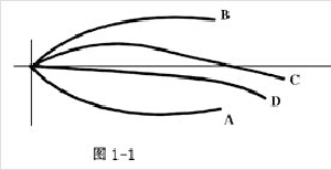
The reasons for the above phenomena are different, and the solutions are also different. We divide it into four categories: first, image blurring, darkening, and tailing caused by the amplitude frequency characteristics and group delay characteristics of the transmission system; 2、 High frequency interference caused by self-excited equipment or environmental electromagnetic interference; 3、 Low frequency interference caused by improper handling of the system power ground wire; 4、 Double reflection and unstable display caused by impedance mismatch of equipment, transmission system or connectors. This article first analyzes the principle of fuzzy tailing phenomenon and provides some solutions. Other situations will be discussed in the future. The causes of fuzzy tailing and dimming can be theoretically divided into two parts. The first is the amplitude frequency characteristics of the signal during transmission, which are caused by insufficient bandwidth and result in blurring and dimming; The second is the tailing phenomenon caused by the group delay characteristics during the transmission process. The amplitude frequency characteristic, in short, refers to the relationship between different frequency components and amplitude attenuation. Taking the 1024 × 768 resolution as an example, it is generally believed that its bandwidth is between 90-120MHz, so we are concerned about the attenuation situation of 100 meters and 100MHz. As far as matrix switches and distributors are concerned, they both have a certain level of improvement and driving ability, which is not a problem for signal transmission. However, considering the loss of connectors, this improvement and driving ability will not be considered in the design and analysis of transmission systems. At present, the problems that cause blurring, dimming, and tailing are mainly concentrated in the transmission cables, because the attenuation of the cables used in transmission is in the form of an inverse number in terms of amplitude frequency characteristics. (As shown in Figure A curve)

The higher the frequency, the greater the attenuation. The specific indicators are shown in the table below:
SYV-75-2 | SYV-75-3 | SYV-75-1 | LG-RG59/5 | |
1MHZ/100米 | -3dB | -2.2dB | -1.2dB | -1dB |
100MHZ/100米 | -22dB | -15dB | -10dB | -8dB |
200MHZ/100米 | -38dB | -24dB | -15dB | -12dB |
外径尺寸 | 15mm | 22mm | 18mm |

Due to the attenuation of each frequency sub variable, the image becomes dark (insufficient brightness) and blurry. To improve this situation, the characteristic curve of the transmission device should be logarithmic, as shown in curve B in Figure 1-1. However, it is not possible to achieve this ideal state in circuit practice, and it generally follows a parabolic shape as shown in the C curve in Figure 1-1. The synthesized result shows the D curve in Figure 1-1. We generally care about the synthesized shaping bandwidth, such as using a long line driver to ensure a transmission bandwidth of 80-120MHz, which can significantly improve dimming, blurring, and other situations, ensuring the transmission and display of its high-frequency components. There are also some other brands of drives that, due to design and various reasons, have a narrow bandwidth of around 30-50MHz. Although this has improved, it has not solved the fundamental problem.
Group Delay refers to the characteristic parameters of the transmission system during signal transmission, which are not purely resistive due to the presence of distributed parameters, but rather composed of resistance, capacitance
The network composed of inductors, therefore, different frequency components have different arrival times or phase differences when transmitted in the same medium. The specific mathematical model and analysis will not be discussed in detail here, as far as the actual results generated are concerned. This group delay characteristic can cause a delay in the signal waveform, resulting in tailing. As shown in Figure 2-1. In transmission equipment, to solve the problem of group delay, it is necessary to pre emphasize the transmission system, that is, pre distortion, as shown in Figure 2-2. The synthesized waveform will have a significant improvement, as shown in Figure 2-3. Different cables and transmission distances have different amplitude frequency characteristics and group delay characteristics, which should be adjusted according to different situations. According to our research, the better the amplitude frequency characteristics of the transmission system, the better its group delay characteristics. Generally speaking, the thicker the line, the smaller the attenuation and tailing
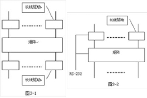
In the absence of compensation, the RGBHV signal (100MHZ) with a resolution of 65Hz 1024 x 768 can theoretically be transmitted using SYV-75-3 cables for only 20 meters, and SYV-75-5-1 cables can only transmit over 30 meters. However, in engineering practice, most engineers and users believe that images transmitted with -6dB in band loss are acceptable, while images transmitted with -9dB in band loss are tolerable. However, the group delay characteristics must be adjusted for delay pre emphasis to solve the tailing problem. Long line drive is used to solve the problem of long-distance signal transmission in engineering. It is generally believed that for 3+2 or 3+4 cables, the distance should be controlled at around 20 meters, and for 75-5 cables, it should be controlled at around 50 meters. If the distance is greater than this, a long line drive should be used for compensation. Due to the different specifications and models of cables used in engineering, their DC impedance, equivalent impedance, distributed capacitance, inductance, and other parameters are different. Therefore, compensation must be made for different situations. In theory, adjustment of capacitance, inductance, and resistance can solve this problem. However, in practical applications, the adjustable range of capacitance and inductance is small, and the adjustment amount needs to be consistent for the three signals of R, G, and B. Therefore, it is very difficult to achieve continuous adjustment. Currently, pre designed networks are often used for superposition, that is, phased adjustment is not used for continuous adjustment, but it must be adjustable. If a fixed circuit is used for certain compensation, it cannot meet the different situations on site and should not be called a long line driver. The long-distance drive compensation equipment simulates the anti number curve characteristics of cables based on the attenuation characteristics of different specifications and lengths of cables, and performs gain compensation and group delay adjustment in different levels. The equipment (VGAD-1 * 2CC/L, VGAD-1 * 2CC/LT) can compensate up to 8/16 levels (about 15 meters per level), and the equipment bandwidth can reach 200MHz (without compensation). After adjustment, the transmission system bandwidth can reach 80-120MHz. The VGAD-1 * 2CC/L 8-speed adjustment compensator is designed for 10dB/100m, 100MHz cables, optimizing parameters. It starts adjusting at 20m and reaches its maximum at 100m, while the VGAD-1 * 2CC/LT 16 speed adjustment equipment starts adjusting at 50m and reaches its maximum at 300m. From the current perspective, it can meet the actual engineering requirements. In response to phenomena such as image instability and even black frequency, the long line compensation driver also performs digital correction on the synchronization signal (ADSP, which is not the focus of this article and will not be elaborated here). The long line compensation driver is easy to operate, and a touch button is designed on the front panel of the device for compensation gear operation. In addition, an RS-232 interface control is added for customers to use the central control or PC to control it, and it can save equipment, as shown in Figure 3-1. For a matrix switch, the length of the input line and the length of the output line are not equal. When compensating, different compensations should be used in the input part to ensure that the input signal is consistent at the matrix entrance. Due to the inconsistent length of the output line, different compensations should also be adopted for it. There are many devices, and if the scheme in Figure 3-2 is used, the input and output line length information should be notified to the long line driver while completing the switch. Compensating and adjusting it according to different lengths can save equipment and reduce investment.

(转载)
更多案例
- Kedi Intelligent Three Choice for Lhasa Integrated Media Center Launch Station
- Kedi's high-definition and multi format mixed matrix has made a name for itself in the Fuzhou Municipal Party Committee
- Kedi's products have successfully passed the acceptance of the Taishan Nuclear Power Plant project
- Kedi emergency switch stationed at Ningbo Radio and Television Station
- Kedi high-definition multi format matrix for Taipingling Nuclear Power Plant
- Kedi 72 Road 4K60 Matrix for Unicom Tianjin Branch Conference Upgrade and Expansion Project
- Kedi Multi format Matrix Used in Hefei Civil Defense Ground Command Center
- The successful application of Kedi Mixed Moment in the Emergency Command Center of Mianyang Fire Brigade
- Kedi Hybrid Assists the Consultation System of Zhejiang Provincial Department of Natural Resources
- Kedi Multi format Mixed Matrix for Guangdong Provincial Emergency Department


